Departure Board Hardware
How to Build Your Own
· Hardware ·
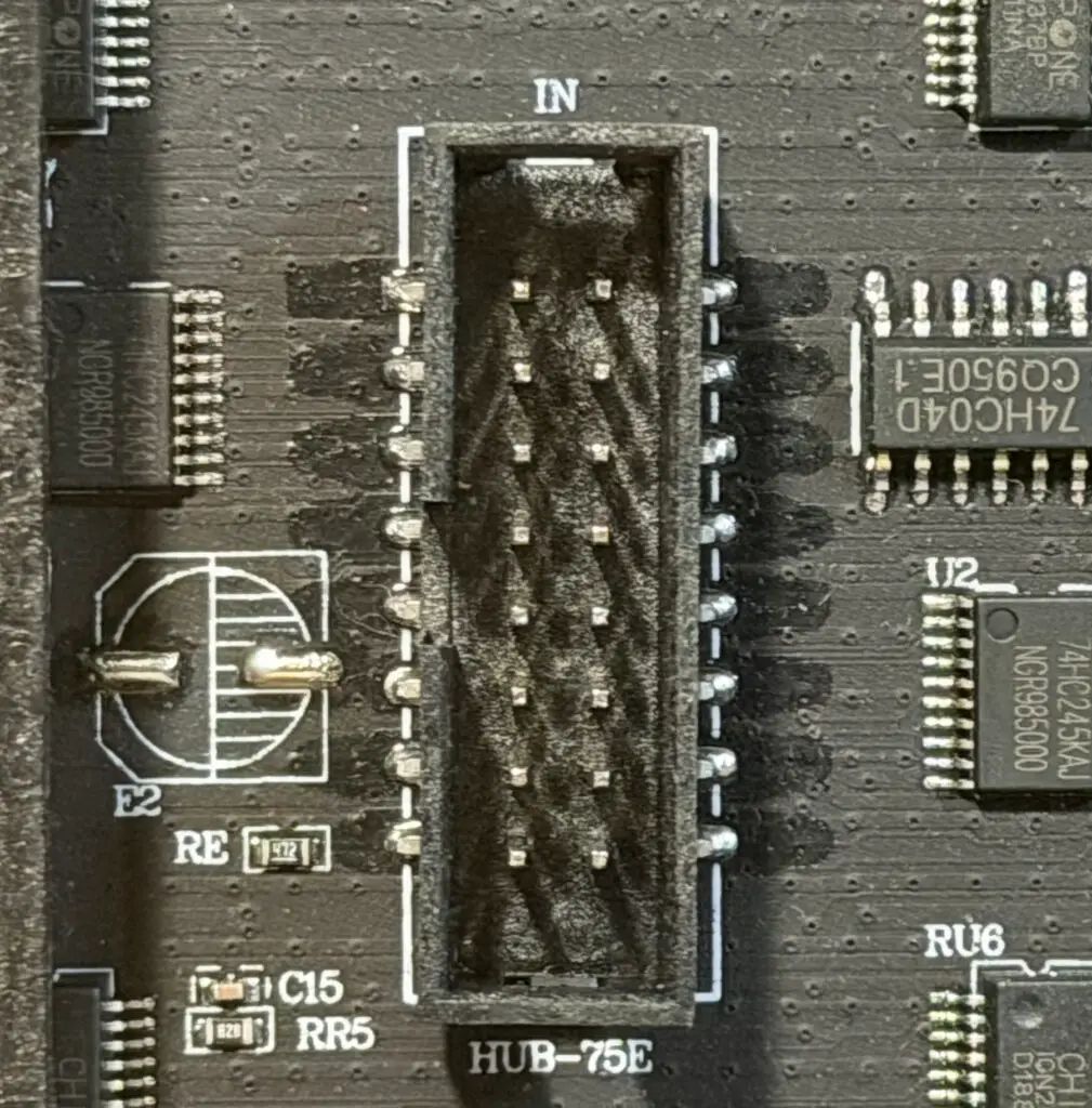
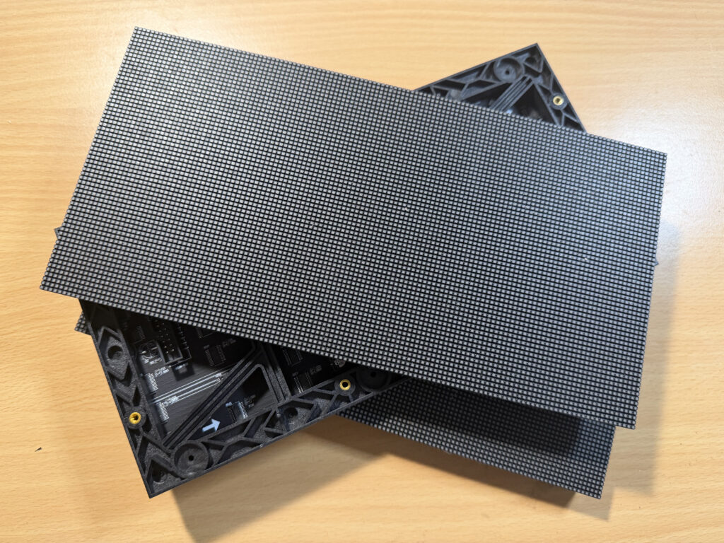
I purchased three P2, 5V, 128*64 pixel colour modules with a HUB75E interface from Ali Express.
Three is a good size to start with. The matrix library I used (hzeller RGB Matrix library) supports more panels and rows.
There are a myriad sellers on Ali Express and elsewhere. I suspect there’s little to differentiate between offerings.
You could purchase a 1GB Raspberry Pi 4 from Pimoroni – I’m not plugging Pimoroni, it’s just they also stock the Bonnet.
I used a Raspberry Pi 4 which was unloved and needed a new purpose.
Note that the RGB matrix library doesn’t yet work with a Pi 5.
In the latest build I’ve used a 3-port driver – at $3 each they’re hard to beat from Electrodragon. More detail on Hzeller’s adapter page
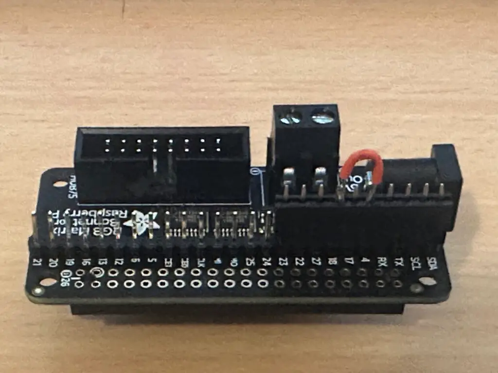
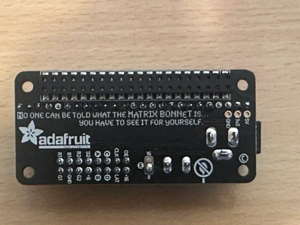
This first version of the project was built with an Adafruit RGB Matrix Bonnet for Raspberry Pi from Pimoroni. Specification on the Adafruit site.
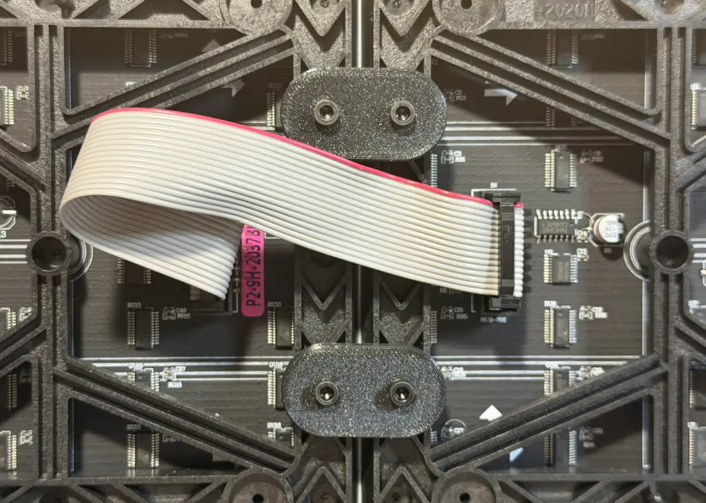
Most sellers provide these with the matrix panels. If you’re making your own then your mantra has to be “Short Is Good”.
I used a bench-top adjustable power supply to provide 5v and up to 5A for the matrix boards and the Raspberry Pi.
The nature of the panels means that current can vary quite wildly. For the departure board with three panels it runs at about 1.5A to 2.0A.
I’d recommend getting something substantial as the “all pixels on” power is just around 3.5A with my configuration… and let’s face it, you’re going to want to play about with it!
The Words about power in the RGB Matrix documentation is worth a read.
I’d highly recommend reading the detail on the hzeller rpi-rgb-led-matrix – Let’s Do It! documentation as it answers every question you can think of.
It’s an awesome resource and fabulous software.
Putting it all together
Adafruit Bonnet
For other adapters see the RGB Matrix – wiring documentation Hzeller supplies.
As highlighted here in the RGB documentation, an optional change to connect pins 4 and 18 on the hat/bonnet can help reduce flicker.
I did this by soldering a row of pins to the bonnet and using a modified connector to make it easy to add/remove the modification.
As highlighted here in the RBG documentation, a change required for the size and type of panels I used.
As a side note, I had to chop some pins off a connector on the Pi as they hit the bonnet – I suspect I may regret that at some point when the Pi gets used for something else.
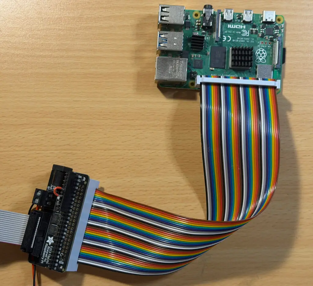
You can buy GPIO-connector cables – this gives you a bit of space to work with and may make constructing a tidy enclosure easier.
Noting the advice about power in the RGB Matrix documentation.
Connect to the panels and the 5v screw-connectors on the Adafruit bonnet to power to the Raspberry Pi.
As noted in the documentation, the Raspberry Pi doesn’t have enough juice to power the panels.
A chance to be creative!
To get you started I’ve provided a basic solution to 3D print joiners.
You can set the key parameters to create a joiner specific to your panels.
Make sure you connect the ‘output’ of one panel to the ‘input’ of another when you’re daisy-chaining them together.
The connectors should be clearly marked, either with text or an arrow indicating In or Out.